TM 55-4920-402-13&P
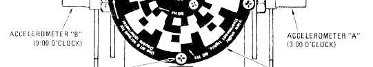
Figure 3-3. Tester Interrupter Placement
stopped under 60 HZ fluorescent lighting,
adjust 900 RPM adjust (fig. 3-2) until these-
cond ring of black and white segments ap-
pear to be stopped.
(3) Connect Balancer Power Cable to the Tester
and ensure Tester Power Cable is still con-
nected to +28 vdc power source,
(4) Set Balancer controls as follows:
(a) INTERRUPTER LOGIC to DOUBLE.
(d)
(b) MAGNETIC PICKUP to COMMON.
(C) RPM RANGE to X10.
1.
(d) RPM TUNE to 180.
(e) FUNCTION to CHANNEL A.
(5) Adjust Tester as follows:
Adjustment with 50 Hz power source for
the fluorescent lights is the same as for 60
Hz with the following exceptions:
The tester strobe disc speed is Calibrated
using the two inner rings of black and
white segments. The third ring from the
outside will appear stopped when the
strobe disc is turning 1714 rpm. The inner
ring (fourth from the outside) will appear
stopped when the strobe disc is turning 923
rpm.
(a)
(b)
(c)
Set MOTOR switch to ON.
Set CAM RATE (RPM) switch to 1800 and
observe that the black and white outer ring
2.
of segments on the strobe disc appear to be
stopped when illuminated by 60 Hz fluores-
cent room lights. If yhe segments are not
stopped under 60 Hz fluorescent lighting,
3.
adjust 1800 RPM adjust (fig. 3-2) until the
outer ring of black and white segments
appear to be stopped.
Set Tester CAM RATE (RPM) and Balancer
The rpm settings of the Balancer and Stro-
bex shall read 1714 and 923 instead of 1800
and 900 respectively.
Ensure rpm readings are still within ±2%,
and IFS meter readings are still within
±10%. The Balancer IPS meter reading
shall be 0.75 @ 1714 rpm and 0.47 @923
rpm.
RPM Tune to 900. RPM RANGE to Xl.
(6) Set Tester rotor for double interrupter with
Observe that the second ring of black and
all six screws in place (fig. 3-3).
white segments on the strobe disc appear to
be stopped when illuminated by 60 Hz
fluorescent room lights. If segments are not
(7) Set Tester CAM RATE (RPM) and Balancer
RPM Tune to 1800 RPM, RPM RANGE to
X10.
3-4
Change 4