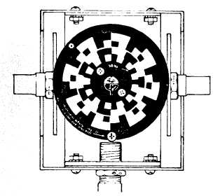
Figure 3-6. Logo at 6:00 O'clock
d. Performance Check of the Strobex Free-Running
Mode (Stopped Image).
NOTE
In the free-running mode, the images will
not be stopped except by precise adjust-
ment of the Strobex RPM dial.
(1)
(2)
Set Strobex MODE switch to C and RPM dial
to 900.
Set Tester CAM RATE (RPM) switch
to 1800 RPM.
Illuminate disc with the Strobex and observe
the logo in the center. Adjust the Strobex
RPM dial for a single stopped image of the
logo. Verify that the RPM dial reads between
855 and 945.
Set MODE switch to D and set Strobex RPM
dial to 180 (1800 RPM).
Illuminate disc and adjust RPM dial for
a stopped double image of the logo.
Verify that the Strobex RPM dial reads
between 171 and 189 (1710 and 1890
RPM).
e. Adjustment There are no internal adjustments to be
made to the Strobex, with the exception of the flash tube
focus adjustment (para. 3-10.c).
3-7. Accelerometer and Magnetic Pickup Checkout.
The accelerometer and magnetic pickup, plus cables
are checked during the Balancer checks in paragraph
3-5. Balancer FUNCTION switch on positions A and B
checks both accelerometers. If the Balancer per-
formance checks are not within specifications perform
paragraph 3-8 below.
TM 55-4920-402-13&P
3-8. Signal Simulator Field Operational Checkout. The
Signal Simulator, P/N B4305, will be very useful as it
quickly verifies all all functions of the Vibrex Text
Set. This will quickly isolate the fault to either the
cables and transducers or the Balancer/Phazor cir-
cuits in unit.
a. Performance Check of Balancer/Phazor Circuit.
NOTE
No other cables are connected to the
Balancer unit. Signal Simulator connectors
may loosen on Balancer cable receptacles
during testing. Check Periodically and
retighten as necssary.
(1) Connect Signal Simulator B4305 big
cable connector into either accelerometer
cable receptacle and small cable connec-
tor into magnetic pickup cable receptacle
on Balancer unit.
(2) Connect Balancer power cable to 28 vdc,
3 amps minimum power source. Observe
polarity pins A(-) and B(+) if portable dc
power supply is used. Verify that at
least one lamp in Phazor ring of lights is
illuminated. (If not, see Table 3-1).
(3) Set the following controls as follows:
(a) FUNCTION to A CHANNEL.
(b) MAGNETIC PICKUP to COMMON.
(c) RPM RANGE to X1.
(d) INTERRUPTER LOGIC to SINGLE.
NOTE
The older Balancer units (without the A
suffix) are switched automatically to Dou-
ble Interrupter Logic when the 135M-10
Strobex is plugged in. Therefore, Phazor
testing and tuning of Balancer unit must be
accomplished without the Strobex plugged
in, so as to realize the simple Interrupter
Logic.
(4) Adjust Balancer RPM TUNE dial to the
lowest RPM (540) reading as shown on
Signal Simulator nameplate.
NOTE
When pressing VERIFY TUNE button,
hold button a minimum of 5 seconds due to
slow reaction time of Phazor at lower RPM.
(5)
Press TEST button and check that the
Phazor 12:00 clock light is lighted.
Release TEST button. (If not, see Table
3-1).
Change 4
3-7