
0037 00
TM 1-4920-433-13&P
NOTE
During installation of components same hardware should be used so as to maintain original
integrity of shop set.
INSPECTION OF INSTALLED ITEMS
CABINETS( A) AND (B) HARDWARE
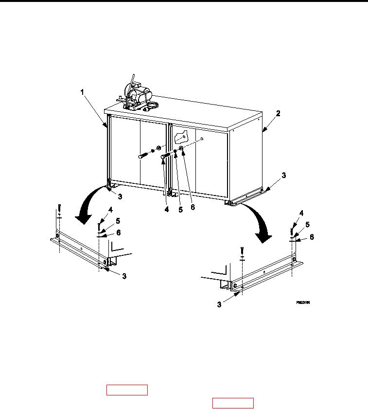
Figure 1.
Cabinets (A) and (B) Hardware.
Inspect cabinet assembly integration hardware (Figure 1) for rust, cracks, and rounded heads. Replace as nec-
essary.
REMOVAL
CABINETS( A) AND (B) HARDWARE
1.
Remove kick plate IAW (WP 0036 00, Kick Plate, REMOVAL).
2.
Remove slides, drawers, and shelves as necessary IAW (WP 0036 00, Drawers, Slides, And Shelves,
REMOVAL ).
3.
Remove four bolts (Figure 1, Item 4), four lock washers (Figure 1, Item 5), and four lat washers (Figure 1,
Item 6) detaching two cabinet brackets (Figure 1, Item 3) from shelter loor.
4.
Remove two bolts (Figure 1, Item 4), two lock washers (Figure 1, Item 5), and two lat washers (Figure 1, Item
6) detaching cabinets (A) (Figure 1, Item 1) and (B) (Figure 1, Item 2) from shelter wall.
0037 00-2