
TM 1-4920-440-13&P
0051 00
WARNING
HIGH VOLTAGE exists in electrical system of shop. All electrical inspections, repairs, or
replacements will be performed with power OFF and only by a qualiied electrician. Serious
shock hazards exist which could result in INJURY OR EVEN DEATH to personnel.
REMOVAL
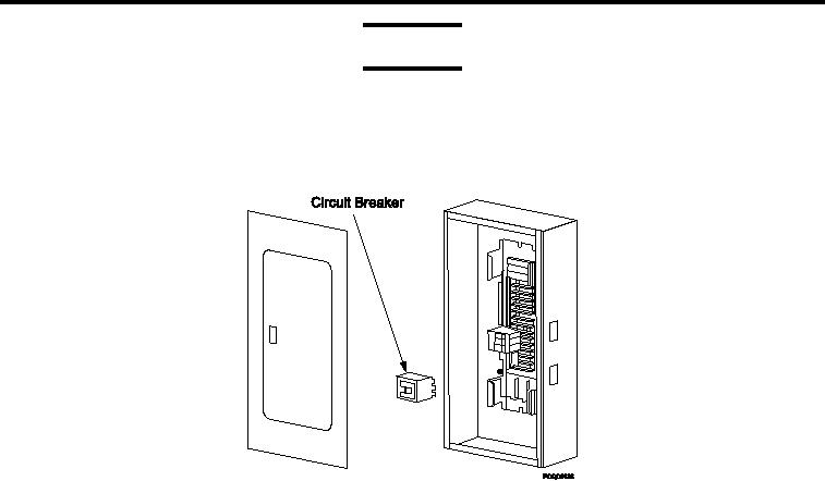
Figure 2.
Replacing Circuit Breakers.
1.
Move all circuit breakers to OFF position and tag.
2.
Mark and disconnect wires from circuit breaker that will be removed.
NOTE
Do not completely remove screw. Only loosen it enough to allow removal of circuit breaker.
3.
Loosen screw securing circuit breaker.
4.
Pull circuit breaker from bus bar and remove from circuit breaker box.
INSTALLATION
1.
Position circuit breaker and tighten screw.
2.
Connect wires.
3.
Attach panel board to circuit breaker box with four screws and four washers.
NOTE
This procedure covers obsolete NQOB circuit breaker panel and new NQOD circuit
breaker panel. These units are distinguishable by nameplates attached to panel boards.
The following steps, Steps 4 through 5, pertain to NQOB model circuit breaker panels only.
4.
Install circuit breaker panel cover to panel board
5.
Move clamp ingers to closed position.
6.
Move all circuit breakers to ON position.
END OF WORK PACKAGE
0051 00-3/4 blank