
0039 00
TM 1-4920-441-13&P
INSPECTION OF INSTALLED ITEMS
CABINETS (F) HARDWARE (1036058)
Figure 4.
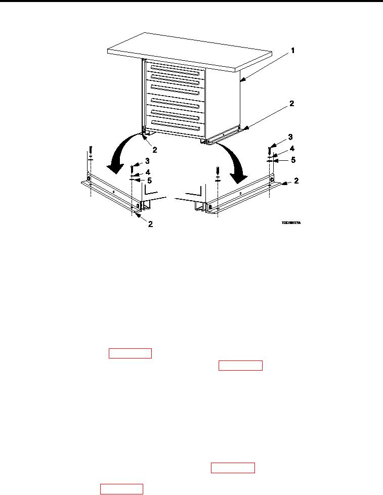
Cabinet (F) Hardware (1036058).
NOTE
Cabinet (F) is an additional cabinet installed in the 1036058 coniguration. The SC4920-
99-CLA69 coniguration does not contain this cabinet assembly.
Inspect cabinet assembly integration hardware (Figure 4) for rust, cracks and rounded heads. Replace as nec-
essary.
REMOVAL
CABINETS (F) HARDWARE (1036058)
1.
Remove kick plate IAW WP 0038 00, Kick Plate, REMOVAL .
2.
Remove drawers, slides, and shelves as necessary IAW WP 0038 00, Drawers, Slides, And Shelves,
REMOVAL .
3.
Remove four bolts (Figure 4, Item 3), four lock washers (Figure 4, Item 4), and four lat washers (Figure 4,
Item 5) detaching two cabinet brackets (Figure 4, Item 2) from shelter loor.
INSTALLATION
CABINETS (F) HARDWARE (1036058)
1.
Install four bolts (Figure 4, Item 3), four lock washers (Figure 4, Item 4), and four lat washers (Figure 4, Item
5) securing two cabinet brackets (Figure 4, Item 2) to shelter loor.
Torque bolts (Figure 4, Item 3) 160-190 in. lbs.
2.
3.
Install slides, drawers, and shelves as necessary IAW WP 0038 00, Drawers, Slides, And Shelves,
INSTALLATION .
4.
Install kick plate IAW WP 0038 00, Kick Plate, INSTALLATION.
0039 00-8