
0039 00
TM 1-4920-441-13&P
INSPECTION OF INSTALLED ITEMS
CABINETS (C), (D) AND (E) HARDWARE (SC4920-99-CLA69)
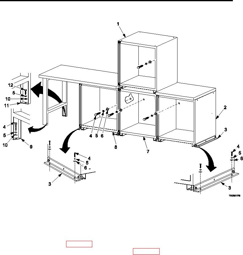
Figure 2.
Cabinets (C), (D) and( E) Hardware (SC4920-99-CLA69).
Inspect cabinet assembly integration hardware (Figure 2) for rust, cracks and rounded heads. Replace as nec-
essary.
REMOVAL
CABINETS (C), (D) AND (E) HARDWARE (SC4920-99-CLA69)
1.
Remove kick plate IAW WP 0038 00, Kick Plate, REMOVAL .
2.
Remove drawers, slides, and shelves as necessary IAW WP 0038 00, Drawers, Slides, And Shelves,
REMOVAL .
3.
Remove lag bolt (Figure 2, Item 12), lock washer (Figure 2, Item 5), and lat washer (Figure 2, Item 10)
detaching open bench leg (Figure 2, Item 11) from shelter loor.
4.
Remove bolt (Figure 2, Item 4), lock washer (Figure 2, Item 5), and lat washer (Figure 2, Item 10) detaching
open bench leg (Figure 2, Item 9) from shelter loor.
5.
Remove four bolts (Figure 2, Item 4), four lock washers (Figure 2, Item 5), and four lat washers (Figure 2,
Item 6) detaching two cabinet brackets (Figure 2, Item 3) from shelter loor.
0039 00-4