
TM 1-4920-924-13&P
OPERATOR INSTRUCTIONS
AVIATION SHOP EQUIPMENT CONTACT MAINTENANCE (AV SECM) SYSTEM
DESCRIPTION AND USE OF OPERATOR CONTROLS AND INDICATORS
7
1
4
3
5
6
Inverter Power
OFF
Power
Low Battery
OFF
On/Off
ON
Overload
High Temperature
A.C. Wiring Compartment
Power Inverter
Main
D.C. Input Wiring Compartment
output
breaker
h
000004
2
MULTI00124
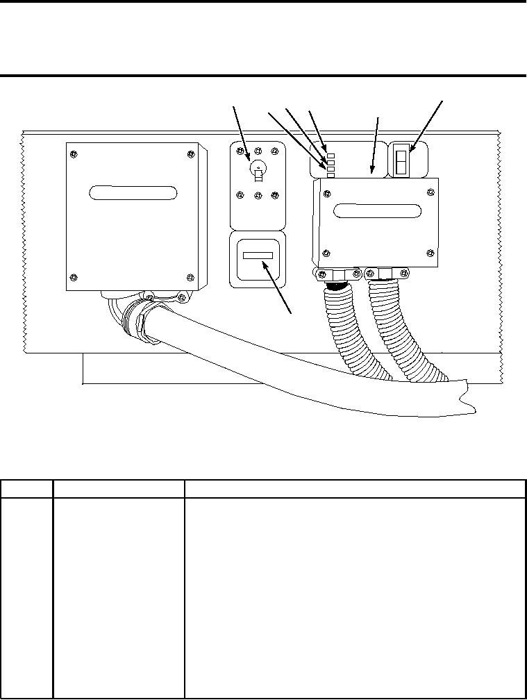
Figure 1. Inverter Controls and Indicators
Table 1. Inverter Controls And Indicators
KEY
CONTROL/INDICATOR
FUNCTION
1
Main Output Breaker
A protective AC output circuit breaker rated at: 20 amps per phase.
Switch
2
Hour Meter
Displays the total amount of time the inverter has been operated over
its lifetime.
3
Inverter Power Indicator
LED indicator light that illuminates when the inverter is operating.
Light
4
Low Battery Indicator Light LED indicator light that illuminates when the inverter has turned off due
the incoming DC voltage dropping below the 21VDC threshold.
5
Overload Indicator Light
LED indicator light that illuminates when the inverter has turned off due
to an excessive load on the inverter's output.
6
High temperature Indicator LED indicator light that illuminates when the inverter has turned off due
Light
to excessive internal heat.
7
On/Off Power Switch
The inverter's main on/off power switch.
END OF WORK PACKAGE
00041/blank