compressor unit should load at a minimum pressure of
2,300 psig ( 1 5847 kPa). Air compressor unit should
unload at a maximum pressure of 3,300 ± 50 psig
(22,392 kPa). If air compressor loads or unloads at an
incorrect pressure, refer to PRESSURE SWITCH
ADJUSTMENT (Section V).
k.
Push ENGINE THROTTLE CONTROL to
the idle position. Disengage clutch by pulling CLUTCH
operating rod away from control panel.
l.
Allow engine to run without a load at a
maximum speed of 1,400 rpm (1,400 r/min) for
approximately five minutes.
m.
Push ENGINE TIHROTTLE CONTROL
completely in. Turn MASTER SWITCH 45° ccw.
n.
To drain the air from the air compressor
system, open the DEHYDRATOR BLEED VALVE,
mechanical filter drain valve (II), and service hose bleed
valve (13).
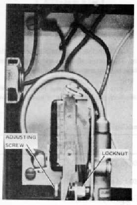
5-3.
Pressure Switch Adjustment (Figure 5-1). The
pressure switch is located in the unloader control box
(Figure 1-1). Unfasten and raise cover of control box.
To adjust pressure switch actuating point, proceed as
follows:
Figure 5-1. Pressure Switch Adjustment
a.
Observe
compressor
pressure
gauge
indication when compressor unloads. The air
compressor unit should unload at 3300 ± 100 psi (22,757
± 689 kPa).
b.
Using an open end wrench, or offset
screwdriver, turn adjusting screw clockwise to decrease
switch actuating pressure and counterclockwise to
increase switch actuating, pressure.
c.
Observe service pressure gauge
(4)
indication. With air compressor unit operating under
normal conditions, compressor unit should load at a
minimum pressure of 3,000 psi (20,670 kPa). The air
compressor unit should unload at a maximum pressure
of 3300 psi ± 50 psi.
5-4.
INSPECTION
AND
PREVENTIVE
MAINTENANCE.
Preventive
maintenance
checks,
services,
and
inspection are listed in Table 5-2. Detailed procedures
are contained in following paragraphs. The table lists the
service time in intervals of operating hours. If a check,
service, or inspection procedure should be accomplished
at an interval other than operating hours, the time interval
is listed in the service column.
5-5.
Air Compressor Air Filter (Figure 5-2). The
compressor air cleaner is a dry, replaceable element
type. Service the air cleaner as follows:
a.
Unscrew the winged nut on the top
assembly. Remove the top cover and filter element.
b.
If inside of filter can is dirty, clean with lint
free cloth.
c.
Install cleaned or new element on filter can
base, install filter cover, with the air inlet hole pointing
away from the compressor. Screw wing nut down finger
tight.
5-6.
Engine Air Filter (Figure 5-3). The engine air
filter is an oil bath type. Service the air filter as follows:
a.
Remove supporting band front air cleaner.
b.
Unfasten and remove oil container from air
filter housing.
c.
If oil is dirty, dump oil and dirt from
container.
d.
Clean container with a lint-free cloth using a
hot
water
and
detergent
solution
per
Federal
Specification, P-D-220. Allow oil container to air dry.
5-2