(3)
Valve seat (10) and bleed valve (11) for
nicks and burrs that will cause sticking or
clogging of orifices.
(4)
Spring (4) for breaks and set. Refer to
Table 6-1.
NOTE
Third stage spring (4) differs from the
first, second and accumulator bleed
valve springs (4). Keep separated.
d.
Repair or Replacement. Refer to paragraph 6-
3.c for general repair or replacement instructions.
(1)
Replace a damaged diaphragm.
(2)
Replace a defective spring.
e.
Assembly. To assemble the continuous bleed
valve subassembly, proceed as follows:
NOTE
Repair kits consisting of spring (4),
diaphragm plate (6). diaphragm (7),
orifice screw (8), valve plunger (9), valve
seat (10), and bleed valve (11) are
available for each of the two bleed valve
subassemblies. The kits differ only in
springs (4). Care shall be taken so as
not to assemble the wrong spring. At
overhaul of the bleed valve
subassemblies, these kits shall be used.
(1)
Assemble orifice screw (8), diaphragm (7),
diaphragm plate (6), and secure together
with locknut (5).
(2)
Install bleed valve (11) in bore of valve
seat (10) with tapered end of valve (11)
into bore first. Screw valve seat (10) into
body until head of seat bottoms in body.
Tighten securely.
(3)
Place valve plunger (9) in center hole of
valve seat head (10) making certain small
end of plunger (9) enters the small air
passage hole in seat (10).
(4)
Position diaphragm (7) aligning diaphragm
holes with tapped holes in body (12).
When assembling spring (4), make
certain that proper spring is assembled
for the third stage application. The third
stage spring has free length of 2-3/4
inches, whereas, first and second stage
spring free length is 2 inches. Assemble
the third stage spring in the assembly
that has a 3 stamped into the face of
body (12).
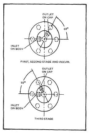
(5)
Assemble proper spring (4) on diaphragm
plate (6). Assemble cap (1) to body (12),
aligning holes so that correct inlet to outlet
relationship is obtained. (See Figure 6-9).
Attach cap to body with lock washers (3)
and cap screws (2). Tighten cap screws
(2) to 16 + 1 pound-inch (1.81 + 0.113
Nm) of torque.
6-30.
Drain Valve Assembly (See Figure 8-27). The
following paragraphs contain disassembly, cleaning,
inspection, repair or replacement and assembly
instructions for the drain valve assembly.
Figure 6-9. Bleed Valve Port Locations
6-36