(3)
Remove nuts (4) and washers (2).
Remove shock mounts from frame (5).
(4)
Remove adaptor (13) from pressure
switch (14). Unscrew and remove
mounting nut and washer securing
pressure switch to box and remove
pressure switch (14). When damaged
only, remove the two lug terminals (15)
from pressure switch leads.
(5)
Remove tubing elbow (16) and connector
(17) from solenoid valve (19) only when
replacement is required, or repair to
solenoid (19) is required. Remove the
corner screw holding box inner panel and
ground leads from solenoid valve (19) and
safety relay (22). Remove diode
subassembly (21) from box. Unscrew and
remove connector (18) and withdraw
solenoid valve (19) from mounting hole.
(6)
Only when necessary, remove terminal
lugs (20) from solenoid switch (19) leads.
(7)
Remove the remaining three screws
attaching box inner panel in place. Lift the
panel from the box and remove nut (26),
lock washer (27), and screw (28) which
attach the safety relay (29) to the box
panel. Only when damaged, unsolder and
remove wire assemblies (22, 20 and 25)
and wire lead (23) from control relay (29).
(8)
To avoid losing parts until ready to
assemble, attach lower inner panel in
place in the control box assembly (30) with
the four corner screws removed during
disassembly.
b.
Cleaning. Refer to paragraph 6-3.a for general
cleaning instructions.
(1)
Clean components with trichloroethane,
per Federal Specification O-T-620, or
equivalent.
(2)
Allow parts to dry thoroughly before
attempting to operate the equipment.
c.
Inspection. Refer to paragraph 6-3.b for general
inspection instructions.
(1)
Test solenoid valve as follows: (a) Using
a multimeter, check for continuity across
coil of the solenoid valve. Meter should
indicate zero (0) ohms.
(b)
Connect solenoid valve coil leads across the
terminals of a 12 volt DC power source. A metallic click
indicates the solenoid valve is operating properly.
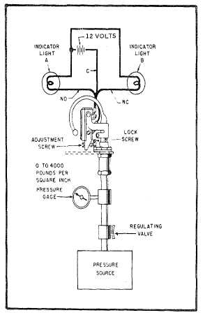
(2)
Test pressure switch as follows:
(a)
Install pressure switch to be tested in test setup
shown in Figure 6-10 or equivalent.
NOTE
The test setup shall incorporate a
master pressure gauge of known
accuracy together with suitable pressure
regulating and controlling apparatus.
The C lead is common, NO lead is
normally open, and the NC lead is
normally closed.
(b)
Adjust pressure source until pressure gauge
indicates 3,300 psig (22,754 KPa).
(c)
Slowly increase pressure until lamp Alights.
Lamp B shall light between 3,250 (22,392 KPa) and
3,350 psig (23,081 KPa).
Figure 6-10. Pressure Switch Test Setup
6-38