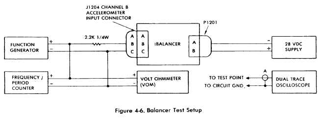
Figure 4-6.
TM 55-4920-402-13&P
d. Functional Test.
(1) Connect Balancer and test equipment as
shown in Figure 4-6.
(2) Set Balancer FUNCTION switch to B, R.P.M.
RANGE switch to X10, and R.P.M. TUNE dial to 999.
(3) Connect oscilloscope to function generator
output and set up function generator for a sine wave
output of 166 Hz at 80 mV rms.
(4) Press and hold VERIFY TUNE switch and
adjust frequency of function generatar for a peak in-
dication on IPS meter. Verify that frequency /peroid
counter indicates 166.6 ± 3.3 Hz. Release VERIFY
TUNE switch.
(5) Adjust output of function generator (do not
change frequency) for a full scale indication on IPS
meter. Verify that VOM indicates 115 mV ± 5%.
(6) Disconnect oscilloscope from function
generator and set up oscilloscope to measure
amplitude of signal at each test point listed in Table 4-
3, Part A, and illustrated in Figure 4-5. Verify that
oscilloscope indication correspond to Table 4-3.
(7) Set R.P.M. RANGE switch to X1.
(8) Connect oscilloscope to function generator
and set function generator output to 16.66 Hz at 11.5
mV.
(9) Press and hold VERIFY TUNE switch and
adjust frequency of function generator for peak indica-
tion on IPS meter. Verify that frequency/period
counter indicates 16.66 ± 0.33 Hz. Release VERIFY
TUNE switch.
(10) adjust output of function generator (do not
change frequency) for a full scale indication on IPS
meter. Verify that VOM indicates 11.5 mV ± 5%.
(11) Disconnect oscilloscope from function
generator and set up oscilloscope to measure
amplitude of signal at each test point listed in Table 4-
3, Part B. Verify that oscilloscope indications corres-
pond to Table 4-3.
(12) Set R.P.M. RANGE switch to X10 and
R.P.M. TUNE dial to 100.
(13) Press and hold VERIFY TUNE switch and
adjust frequency of function generator for a peak in-
dication on IPS meter. Verify that frequency/period
counter indicates 16.66 ± 0.33 Hz. Release VERILY
TUNE switch.
(14) Adjust output of function generator (do not
change frequency) for a full scale indication on IPS
meter.
(15) Set up oscilloscope to measure amplitude of
signal at each test point listed in Table 4-3, Part C.
Verify that oscilloscope indications correspond to
Table 4-3.
(16) If Functional tests indicate all circuits are
functioning properly, peform adjustments in
paragraph 4-20a to align balancer section.
(17) Replace cover and disconnect equipment.
4-8.2
Change 8

