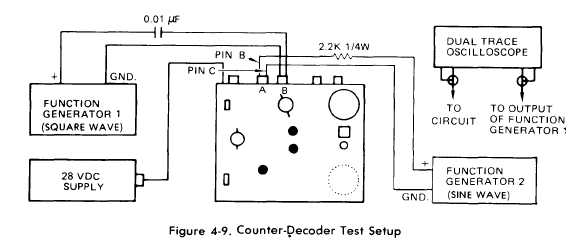
Figure 4-9.
TM 55-4920-402-13&P
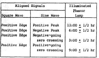
(8) Refer to Table 4-6 and carefully adjust phase
of function generator 1 relative to function generator
2. Verify that correct Phazor lamp is illuminated.
(9) Replace cover and disconnect equipment.
Table 4-6. Decode and Display Verification
4-13. Strobex Tests. These tests will determine the
operational capability of the Strobex. Perform per-
formance checks (a) thru(d) only when directed bythe
troubleshooting procedure Table 4-17 or when ap-
plicable.
a. Remove six screws and lockwashers and pull rear
cover out of case.
CAUTION
Disconnect +28 vdc power source before
making resistance checks with a
multimeter.
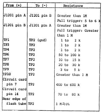
b. Perform Strobex resistance checks in accordance
with Table 4-7. Figure 4-11 shows the location of
Strobex test points.
Table 4-7. Strobex Resistance Checks
NOTE:RESISTANCE READINGS MAY DIFFER FROM
THOSE SHOWN AS SEMICONDUCTORS EXHIBIT NON-
LINEAR RESISTANCE CHARACTERISTICS
c. Voltage Test.
(l) Connect +28 vdc power supply onlyto
Strobex as shown in Figure 4-10.
(2) Set MODE switch to A and RPM dial to 500.
(3) Use VOM to measure voltage at test points in
Table 4-8 (Trigger pulled).
Change 4
4-10.1


