Table 4-3. Balancer Test Point Measurements
Location Peak-to-Peak (mV)
A
TP1
TP8
TP12
TP11
TP2
TP14
TP13
TP3
285 to 315
285 to 315
76 to 84
95 to 105
95 to 105
475 to 525
570 to 630
2850 to 3105
B
TP1
TP8
TP12
TP11
TP2
TP14
TP13
TP3
36 to 44
36 to 44
63 to 77
79 to 99
79 to 99
540 to 550
540 to 660
2700 to 3300
C
TP1
30 to 40
TP8
30 to 40
TP12
63 to 77
TP11
810 to 990
TP2
81 to 99
TP14
450 to 550
TP13
5400 to 6600
TP3
2700 to 3300
NOTE: READING SPECIFIED ARE THE APPROXIMATE
PEAK-TO-PEAK mV INDICATIONS EXPECTED NOT IN-
TENDED FOR CALIBRATION PURPOSES.
4-12. Phazor Tests. These tests will determine the
operational capability of the Phazor. Perform per-
formance checks (a) thru (p) only when directed by
troubleshooting procedure Table 4-17 or when applic-
ble.
a. Perform Phazor resistance checks as applicable
with Table 4-4. Figure 4-7 shows the location of Phazor
test points.
b. Remove rear cover by removing four screws.
CAUTION
Disconnect +28 vdc power source before
making resistance checks with multimeter.
TM 55-4920-402-13&P
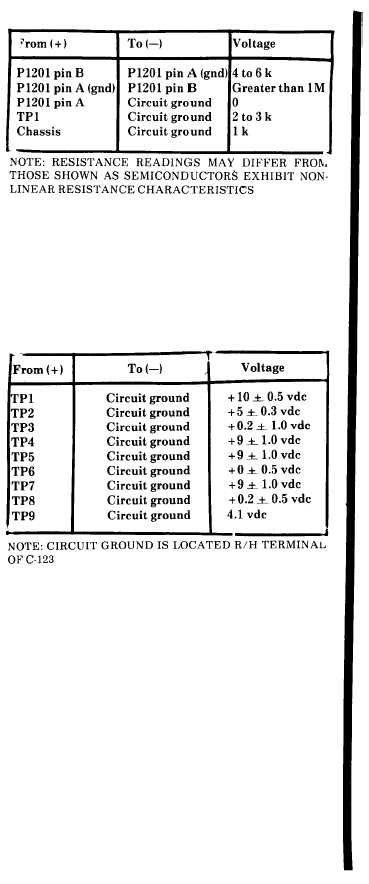
Table 4-4. Phazor Power Supply Resistance Checks
c. Voltage Test.
(1) Connect +28 vdc power supply only to
Balancer as shown in Figure 4-8.
(2) Use VOM to measure voltages at test points
in Table 4-5.
Table 4-5. Phazor Voltage Checks
d. Sample Command Test.
(1) Connect Balancer and test equipment as
shown in Figure 4-8.
(2) Set FUNCTION switch A, R.P.M. RANGE
switch to X10, and INTERRUPTER LOGIC switch to
SINGLE.
(3) Connect oscilloscope to function generator
output and set up function generator for a square
wave output of 600 m. peak-to-peak at 41.7 Hz ± 1
Hz.
(4) Disconnect oscilloscope from function
generator and connect to TP3 (Figure 4-7). Verify that
oscilloscope indication is a + 5 volt spike at 41.7 Hz.
(TEST switch depressed).
e. Phase-Lock Loop Tests.
(1) Connect Balancer and test equipment as
shown in Figure 4-8.
Change 4
4-8.3/(4-8.4
blank)

