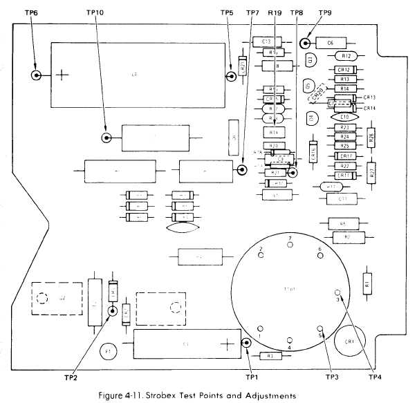
Figure 4-11.
TM 55-4920-402-13&P
d. Oscillator Frequency Test.
(1) Disconnect frequency/period counter and
function generator,
(2) Connect oscilloscope to TP10 (Fig. 4-11). Set
up oscilloscope to sync on EX 60 Hz source and to
measure a 400-volt signal with a 2 ms/division time
base.
(3) Set RPM dial MODE switch to positions in-
dicated in Table 4-9. At each setting, adjust RPM dial
to sync oscilloscope. Verify that RPM dial indicates
value listed in Table 4-9 after syncing.
e. Testing of Locking Oscillator.
(1) Connect Strobex and test equipment as shown
in Figure 4-10.
(2) Connect oscilloscope to function generator
and set up oscilloscope to trigger from positive edge of
function generator output.
NOTE
Sync may be found at more than one point
at each setting.
RPM dial
MODE switch
Synced RPM dial
180
D
171 to 189
360
D
342 to 378
540
D
513 to 567
720
D
684 to 756
900
D
855 to 945
720
C
684 to 756
720
B
684 to 756
Table 4-9. Strobex Oscillator Frequency Check
Change 4
4-10.3