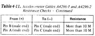
Table 4-11.
TM 55-4920-402-13&P
4-15. Accelerometer and Magnetic Pickup.
a. Accelerometer. These tests will determine the
operational capability of the Accelerometer and Ac-
celerometer Cables. Refer to Figures 4-14 & 4-15 for
schematic diagrams of the Accelerometer and Ac-
celerometer Cables and perform resistance checks in
accordance with Table 4-10 & 4-11, respectively.
Table 4-10. Accelerometer 4177B Resistance Checks
From (+)
To (–)
Resistance
Pin A
Pin B
2 to 3k
Pin A
Pin C
More than 1 M
Pin B
Pin C
More than 1 M
Pin A, B, or C
1/4-28 stud
More than 10 M
Table 4-11. Accelerometer Cables A4296-1 and A4296-2
Resistance Checks
From (+)
Pin A (male end)
Pin B (male end)
Pin C (male end)
Shell (male end)
Shell (female end)
Pin A (male end)
To (–)
Pin A (female end)
Pin B (female end)
Pin C (female end)
Pin A, B, or C
Pin A, B, or C
Pin B (male end)
Resistance
Less than 1 ohm
Less than 1 ohm
Less than 1 ohm
More than 10 M
More than 10 M
More than 10 M
b. Magnetic Pickup. These tests will determined the
operational capability of the Magnetic Pickup and
Magnetic Pickup Cable. Refer to Fig. 4-15 for a
schematic diagram of the Magnetic Pickup Cable and
perform resistance checks in accordance with tables 4-
12 & 4-13, respectively.
Table 4-12. Magnetic Pickup 3030AN Resistance Checks
Table 4-13. Magnetic Pickup Cable A3319-2
Resistance Checks
Figure 4-14. Accelerometer 4177B, Schematic Diagram
Change 4
4-11


