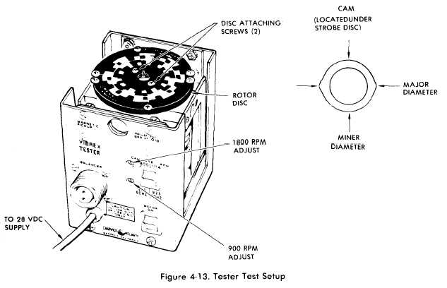
Figure 4-13.
(3) Set function generator output to 10 Hz at 1
volt peak-to-peak.
(4) Set MODE switch to B and RPM dial to 395.
(5) Disconnect oscilloscope from function
generator and connect to TP-9 (Fig. 4-11).
(6) Squeeze and hold trigger. Verify that
oscilloscope display is as shown in figure 4-12A. The
ramp which fires at 60 ms is the oscillator; the ramp
which fires at 100 ms is the square wave input signal
(10 Hz = 100 ins). Release trigger.
f. Testing of Trigger Circuit.
(1) Connect Strobex and test equipment as shown
in figure 4-10.
(2) Connect oscilloscope to function generator
and set up oscilloscope to trigger from positive edge of
function generator output.
(3) Set MODE switch to D and RPM dial to 100.
(4) Disconnect oscilloscope from function
generator and connect to TP10 (Fig. 4-11). Set
oscilloscope to internal trigger, negative slope.
(5) Squeeze and hold trigger. Verify that
oscilloscope display is as shown in figure 4-12B.
Release Trigger.
g. Testing of High-Lo w Intensity Function.
TM 55-4920-402-13&P
(1) Disconnect frequency/period counter and
function generator.
(2) Set MODE switch to D and RPM TUNE dial
to 500.
(3) Connect oscilloscope to rear terminal of
C1201 (22, fig. C-5) large capacitor at rear of case.
(4) Squeeze and hold trigger. Verify that
oscilloscope display is as shown in figure a4-12C.
Release trigger.
(5) Set MODE switch to C.
(6) Squeeze and hold trigger. Verify that
oscilloscope display is within 1 volt of ground. Release
trigger.
(7) Connect oscilloscope to junction of CR1203
(31, fig. C-5) and L1202 (34) (Fig. C-5).
(8) Set MODE switch to D.
(9) Squeeze and hold trigger. Verify that
oscilloscope display is as shown in figure 4-12D.
Release trigger.
(10) Set MODE switch to C.
(11) Squeeze and hold trigger. Verify that
oscilloscope display is as shown in figure 4-12E.
Release trigger.
Change 4
4-10.5

