TM 55-4920-402-13&P
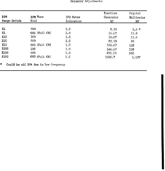
T a b l e 4 - 1 6 .
Ealancer Adjustments
Function
Digital
RPM
RPM Tune
IPS Meter
Generator
Multi meter
Range sw~tch
Dial
Indication
Hz
Mv
xl
500
1.0
8.33
5.9 *
xl
000
(Full
CW)
1.0
16.67
11.8
Xlo
100
1.0
16.67
11.8
Xlo
500
1.0
83.33
59
Xlo
000 (Full Cw)
1.0
166.67
118
Xloo
100
1.0
166.67
118
Xloo
500
1.0
833.33
590
Xloo
000 (Full CW)
1.0
1666.7
1.15V
*
Could be off 30% due to low frequency
NOTE: Frequency and MV readings may vary as much as ± 5% on test equipment listed above for dif-
ferent units tested to obtain 1.0 IPS on meter. Table 4-16 will indicate approximate indications ex-
pected. If one range is way out, one or more of the intergrating capacitors C106 thru C117 could be
faulty if 1.0 cannot be obtained on IPS meter.
(3) Set up function generator for a square
wave output of 600 mV peak-to-peak at 41.7 Hz.
Use oscilloscope inut A to measure signal.
(4) Remove cover by removing four screws.
(5) Connect oscilloscope input B to TP6 (Fig
4-7).
(6) Adjust R117 (Fig. 4-7) until peak of
sawtooth ramp is 5 volts above ground. Bottom
of ramp is approximately 1.5 volts above ground.
(7) Observe that there are 24 sawtooth
ramps for each input square wave.
(8) Adjust R145 so that the last ramp prior
to the positive-going edge of the square wave is
75% of the height of the other 23 sawtooth
ramps.
(9) Disconnect Equipment and Replace
Cover.
c. Strobex Adjustments. Perform this pro-
cedure only when directed by the
Troubleshooting procedures (Table 4-17).
(1) Remove Cover.
(2) Connect + 28 vdc power suppply to
Strobex. (Figure 4-10).
(3) Set Strobex MODE switch to D and
RPM dial to 360.
(4) Connect oscilloscope to TP10 (Fig 4-11).
Set-up oscilloscope to Sync on EX 60 Hz source
and to measure a 400 volt signal with a
2mS/division time base.
(5) Squeeze and hold trigger and adjust R19
(Fig 4-11) until oscilloscope wave shape is sync-
ed.
(6) Disconnect equipment and replace cover.
Change 4
4-16.1

