TM 9-4933-223-13&P
4.
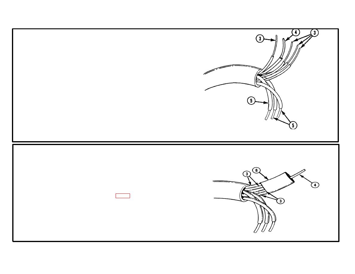
THREE (RED, BLACK, AND BLUE OR ORANGE) WIRES (5).
a. Remove 0.625 in. (1.59 cm) of insulation.
b. Twist exposed end of wire.
5.
FOUR GREEN WIRES (3).
a. Bring to white wire (4).
b. Line up ends of wires.
6.
COMPRESSION CONNECTOR (6).
a. Install over four green wires (3) and white wire
(4) with 0.625 in. (1.59 cm) of white wire
protruding from compression connector.
b. Solder in place using solder (item 16, app D).
3-225


