
TM 9-4933-223-13&P
NOTE
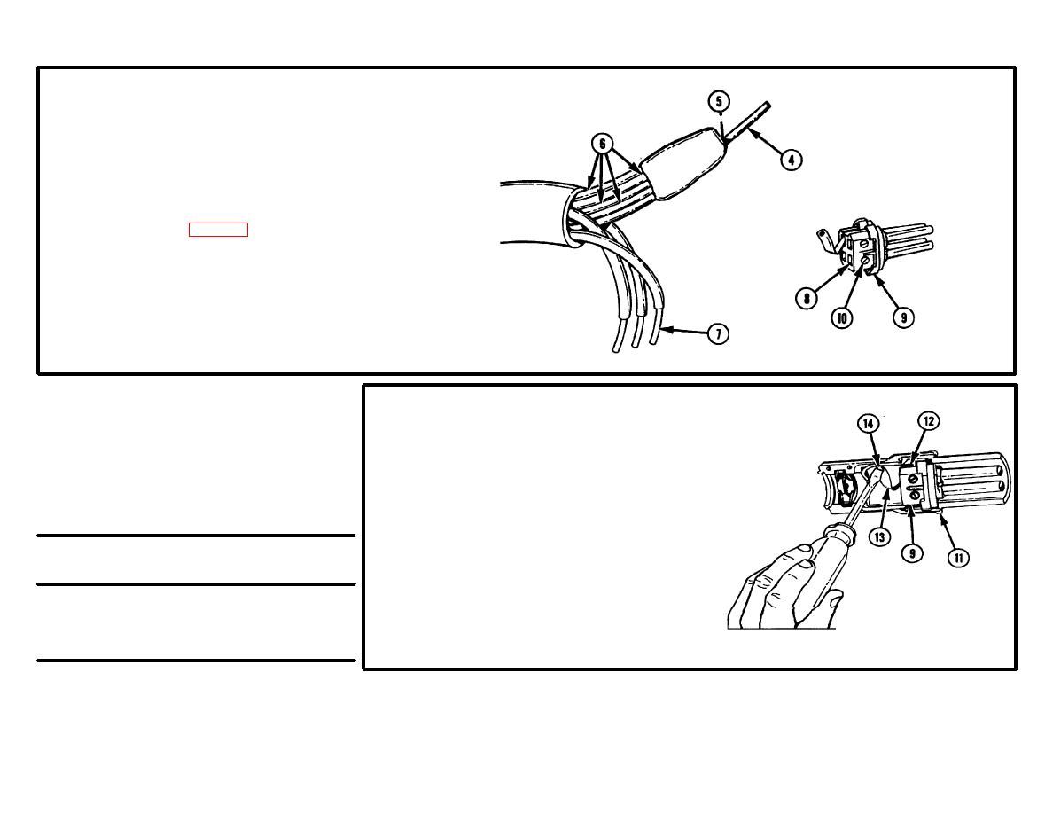
White wire (4) is soldered
into compression connector
(5) along with four green
wires (6).
3.
WHITE WIRE (4) AND THREE (RED, BLACK,
AND BLUE OR ORANGE) WIRES (7). Install in
four contact recesses (8) of insulator assembly
(9) according to table 3-5.
4.
FOUR PRESSURE CONTACT SCREWS (10).
Tighten.
Table 3-5. Wire Polarity
5
INSULATOR ASSEMBLY (9). Install in
lower half of body (11) with wide
NOTE
notch (12) to left (viewed from
Use this table to get
cable side).
correct polarity on
wires.
6
GROUND STRAP (13). Position over
tapped hole in lower half of body
Contact Recess
(11).
Designation
Wire Color
7
SCREW (14). Install.
1
Black
2
Red
3
Blue or Orange
4
White
3-227
