TM 9-4933-223-13&P
3-26.
CABLE ADAPTER ASSEMBLY--MAINTENANCE INSTRUCTIONS (cont)
INSTALLATION (cont)
6.
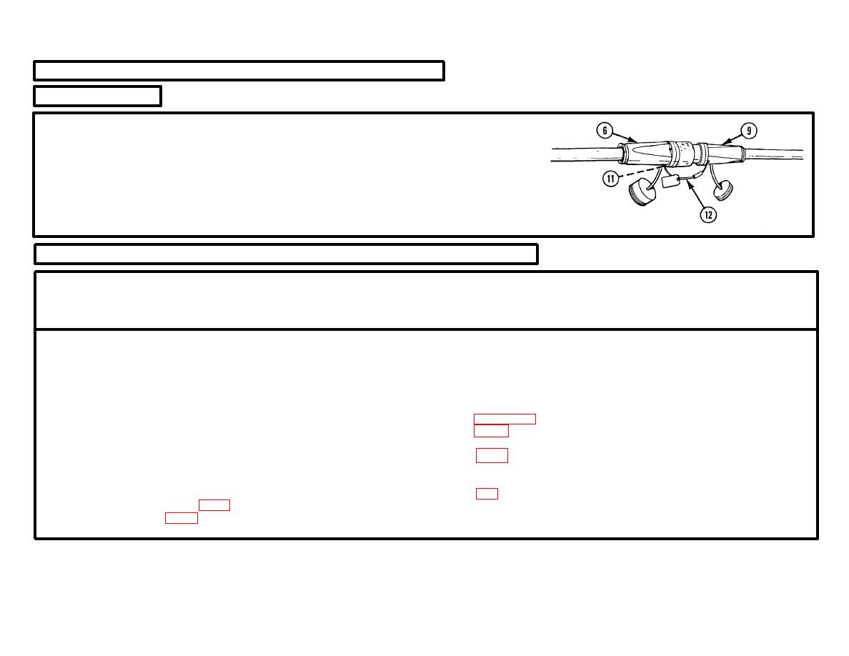
ELECTRICAL PLUG CONNECTOR (MALE) (6) AND FEMALE CONNECTOR (9).
Plug together.
7.
SCREW (11).
a. Remove from electrical plug connector (male) (6) of 120/208V
cable assembly.
b. Assemble through one end of cable assembly (12).
c. Reinstall in electrical plug connector (male) (6).
3-27.
CABLE ADAPTER ASSEMBLY--FEMALE CONNECTOR--MAINTENANCE INSTRUCTIONS
THIS TASK COVERS:
a. Removal
d.
Repair
b. Inspection
e.
Installation
c. Service
INITIAL SETUP
Test Equipment
Bushings (4) (MS3348-4-6L)
Ground socket (M39029/49-329)
Special Tools
Preformed packing (MS29513-132)
Armament repair shop set (SC 4933-95-CL-A21)
Sockets (A, B. C, and N) (4) (M39029/49-331)
Basic aircraft armament repair tool set
References
(SC 5180-95-CL-B09)
Removal tool no. 4 (MS90562-5)
Removal tool no. 6 (MS90562-6)
instructions for cable adapter assembly.
Supplemental aircraft armament repair tool set
(SC 5180-95-CL-B10)
cable adapter assembly.
(SC 5180-95-CL-B10)
Troubleshooting Reference
Materials/Parts
Environmental control units or exhaust
Polishing cloth (item 5, app D)
fans do not operate correctly.
Solder (item 16, app D)
Change 1 3-236


