
TM 9-4940-421-14
b. Cleaning and Inspection.
(2) Examine the pump body and gear for cracks or
(1) Wash all of the parts in cleaning solvent and
breaks and replace a defective oil pump.
dry thoroughly. Use a fiber brush to clean the screen
AR 701582
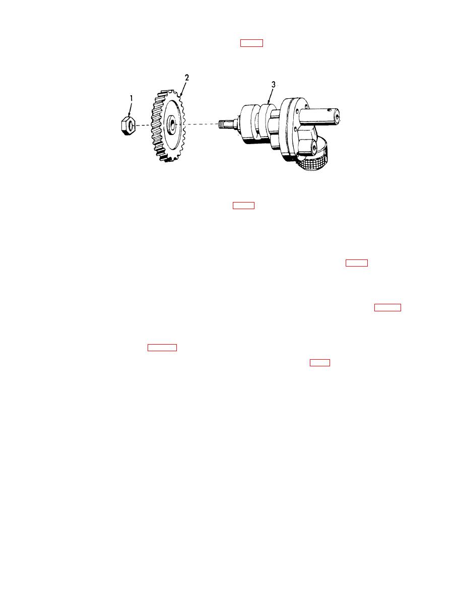
Legend for fig 6-11:
1. Nut
2. Gear
3. Body
b. Removal.
c. Installation.
(1) Remove the gear cover (fig 6-9).
(1) Install the oil pump in the crankcase with the
(2) Remove the setscrew from the left-hand side of
screen facing toward the bottom of the engine. Secure
the crankcase which locks the idler shaft in position.
with the setscrew and pipe plug.
(3) Using a gear puller remove the idler shaft and
(2) Install the woodruff key in the oil pump shaft.
idler gear assembly.
(3) Install the gear (2) and secure with the nut (l).
(4) Remove the three capscrews (1, fig 6-13) and
(4) Apply a thin coat of grease to a new cover
lockwashers (2) that secure the camshaft gear (3) to the
plate gasket and position the gear cover on the
camshaft. Pull the camshaft thrust plunger (7) from
crankcase and secure with capscrews and lockwashers.
the end of the camshaft. Remove the plunger spring (6).
Tighten to 6-9 lbs. ft.
c. Cleaning and Inspection.
(1) Wash the removed gears with cleaning solvent
a. General. The timing-gear train is located at the
and dry thoroughly (app D).
same end of the engine as the flywheel, and is enclosed
(2) Examine the gears for broken, cracked or chip-
in a gear cover. It comprises the governor gear,
ped teeth. Replace any damaged or excessively worn
camshaft gear, crankshaft gear, idler gear and oil
gears.
pump gear. The governor gear can be removed from the
(3) Inspect the idler gear shaft for scoring or pit-
gear train without removing the gear cover. The re-
ting. Remove any roughness with a fine grade of emery
maining gears, with the exception of the crankshaft
cloth.
gear, can be removed after the gear cover is removed.
