
TM 1-4920-433-13&P
0036 00
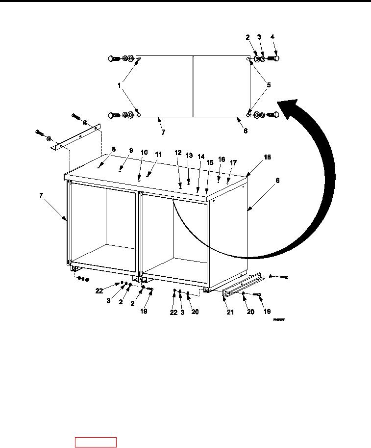
INSPECTION OF INSTALLED ITEMS
4 DRAWER CABINET (C) AND 4 DRAWER CABINET (D)
Figure 4.
Cabinet (C) and Cabinet (D).
1.
Inspect cabinet assembly and work surface (Figure 4) for damage. Replace as necessary.
2.
Inspect all cabinet assembly hardware (Figure 4, Item 2, 3, 4, 19, 20 and 22) for rust, cracks and rounded
heads. Replace as necessary.
REMOVAL
4 DRAWER CABINET (C) AND 4 DRAWER CABINET (D)
1.
Remove kick plate IAW (Kick Plate, REMOVAL).
2.
Remove drawers, slides, and shelves as necessary IAW (Drawers, Slides, And Shelves, REMOVAL).
3.
Remove hardware attaching cabinet (C) (Figure 4, Item 7) and cabinet (D) (Figure 4, Item 6) to shelter loor
and wall IAW (WP 0037 00, Cabinets (C) and (D) Hardware, REMOVAL).
4.
Remove four lag bolts (Figure 4, Item 4), four lock washers (Figure 4, Item 3), and four lat washers (Figure 4,
Item 2) detaching work surface (Figure 4, Item 18) from cabinet (C) (Figure 4, Item 7) and cabinet (D) (Figure
4, Item 6).
0036 00-7