
0011
TM 1-4920-924-13&P
AVIATION SHOP EQUIPMENT CONTACT MAINTENANCE (AV SECM) SYSTEM MAINTENANCE
INSTRUCTIONS FOR CURBSIDE ASSEMBLY - (CONTINUED)
REMOVE
1
7
3
2
6
5
4 3
2
SECM0006
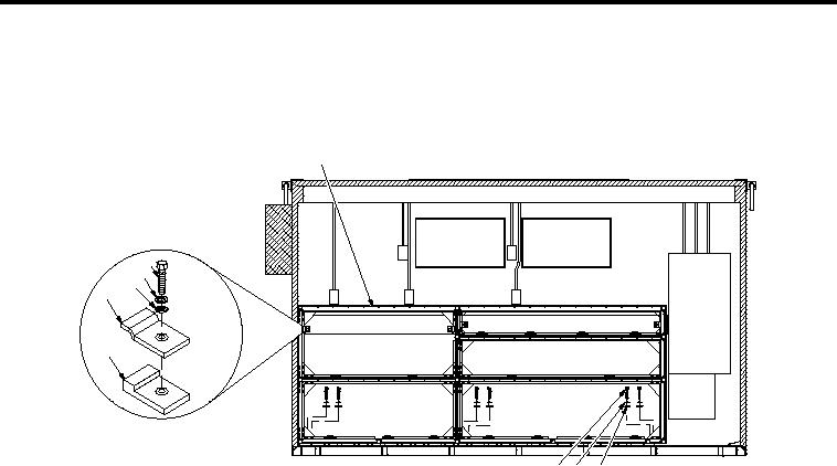
Figure 2. Curbside Assembly Removal
1.
On curbside wall, remove four 1/2-20 X 1.75 inch hex head bolts (Figure 2, Item 7), four 1/2 inch
spring lock washers (Figure 2, Item 3), four 1/2 inch lat washers (Figure 2, Item 2), four hold down
clamps (Figure 2, Item 6) and four spacers (Figure 2, Item 5) securing SECM curbside rack assembly
(Figure 2, Item 1) to curbside wall.
2.
On bottom shelf of SECM curbside rack assembly (Figure 2, Item 1), remove six 1/2-20 X 1.00 inch hex head
bolts (Figure 2, Item 4), six 1/2 inch spring lock washers (Figure 2, Item 3) and six 1/2 inch lat washers
(Figure 2, Item 2) securing SECM curbside rack assembly (Figure 2, Item 1) to shelter loor.
3.
Slide SECM curbside rack assembly (Figure 2, Item 1) toward middle of shelter clearing any obstacles.
END OF TASK
DISASSEMBLE
WARNING
SECM curbside rack assembly weights 310 lbs. disassemble and assemble rack assembly in
layers while inside of van to allow for safe lifting IAW MILSTD- 1472
NOTE
There will be one spring sheet nut used for every connection of aluminum rail to corner casting
throughout the SECM curbside rack assembly. Clips lock corner castings and aluminum rails
together. Ensure all spring sheet nuts are retained for use with reassembly.
It is only necessary to disassemble the SECM curbside rack assembly to the extent necessary
to remove damaged component(s). Upon removal of damaged component(s), proceed to the
applicable reassembly heading(s).
00113