
0011
TM 1-4920-924-13&P
AVIATION SHOP EQUIPMENT CONTACT MAINTENANCE (AV SECM) SYSTEM MAINTENANCE
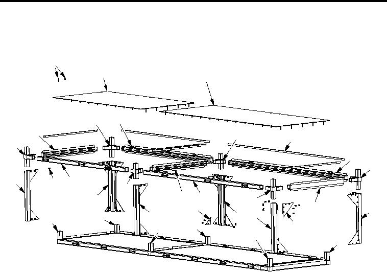
INSTRUCTIONS FOR CURBSIDE ASSEMBLY - (CONTINUED)
Third Shelf
1
2
3
32
31
30
4
5
29
6
7
25
28
26
22
19
18
24
12
10
17
8
20
13
15
23
27
11
16
21
14
9
SECM0009
Figure 5. Curbside Assembly Third Shelf
NOTE
Mark or number parts to ensure parts are installed in the same orientation and location they
were removed from.
1.
Remove sixty-four countersunk screws (Figure 5, Item 1) and sixty-four speed nuts (Figure 5, Item 26) from
support plates (Figure 5, Item 2 and 3).
2.
Remove two support plates (Figure 5, Item 2 and 3) and six shims (Figure 5, Item 5).
3.
Remove four countersunk screws (Figure 5, Item 1), four speed nuts (Figure 5, Item 26), and two small
gussets (Figure 5, Item 17).
4.
Remove seventy-two countersunk screws (Figure 5, Item 1), seventy-two speed nuts (Figure 5, Item 26),
and eighteen large gussets (Figure 5, Item 11).
NOTE
Spring sheet nuts lock corner castings and aluminum rails together at every connection of
aluminum rail and corner castings. Ensure all spring sheet nuts are retained for use with
reassembly.
00117