
0011
TM 1-4920-924-13&P
AVIATION SHOP EQUIPMENT CONTACT MAINTENANCE (AV SECM) SYSTEM MAINTENANCE
INSTRUCTIONS FOR CURBSIDE ASSEMBLY - (CONTINUED)
5.
To remove third shelf, loosen and remove bottoms of six aluminum rails (Figure 5, Item 8, 13, 15, 20, 24 and
28) from six corner castings (Figure 5, Item 9, 14, 16, 21, 23 and 27) and set third shelf aside.
6.
Remove six aluminum rails (Figure 5, Item 8, 13, 15, 20, 24 and 28) from six corner castings (Figure 5, Item
4, 7, 12, 22, 29 and 31).
7.
Loosen and separate two corner castings (Figure 5, Item 7 and 12) from aluminum rails (Figure 5, Item
6 and 18).
8.
Loosen and separate two corner castings (Figure 5, Item 4 and 22) from aluminum rails (Figure 5, Item
6 and 18).
9.
Loosen and separate two corner castings (Figure 5, Item 7 and 12) from aluminum rail (Figure 5, Item 10).
10.
Loosen and separate two corner castings (Figure 5, Item 29 and 31) from aluminum rails (Figure 5, Item
25 and 32).
11.
Loosen and separate two corner castings (Figure 5, Item 4 and 22) from aluminum rails (Figure 5, Item
25 and 32).
12.
Loosen and separate two corner castings (Figure 5, Item 29 and 31) from aluminum rail (Figure 5, Item 30).
13.
Loosen and separate two corner castings (Figure 5, Item 4 and 22) from aluminum rail (Figure 5, Item 19).
Fourth Shelf
1
2
3
4
23
24
5
6
7
8
9
22
21
20
19
10
18
16
17
15
11
14
12
13
SECM0010
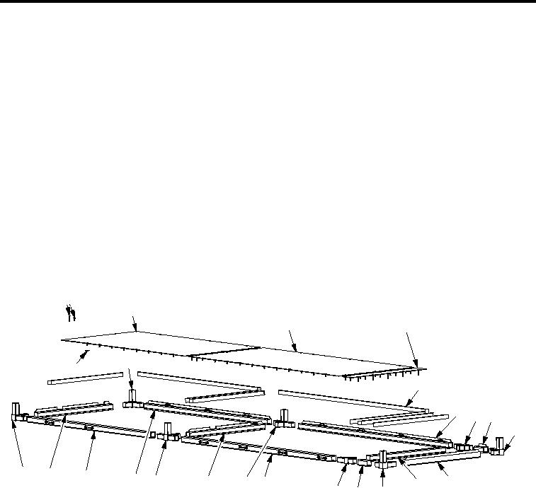
Figure 6. Curbside Assembly Fourth Shelf
NOTE
Mark or number parts to ensure parts are installed in the same orientation and location they
were removed from.
1.
Remove seventy countersunk screws (Figure 6, Item 1) and twenty speed nuts (Figure 6, Item 24) from
support plates (Figure 6, Item 2, 3 and 4).
2.
Remove three support plates (Figure 6, Item 2, 3 and 4) and eight shims (Figure 6, Item 5).
NOTE
Spring sheet nuts lock corner castings and aluminum rails together at every connection of
aluminum rail and corner castings. Ensure all spring sheet nuts are retained for use with
reassembly.
00118