
0014
TM 1-4920-924-13&P
AVIATION SHOP EQUIPMENT CONTACT MAINTENANCE (AV SECM) SYSTEM MAINTENANCE
INSTRUCTIONS FOR STRAP FASTENER LOOPS - (CONTINUED)
27. Remove strap fastener loops (Figure 12, Item 17) and drill one 3/16 inch hole at eight center punched
marks (Figure 12, Item 1, 2, 3, 4, 5, 6, 7 and 8).
28. Install four strap fastener loops (Figure 12, Item 17) to slide out shelf assembly (Figure 12, Item 11) by
installing eight 11/64 inch blind rivets (Figure 12, Item 16) into mounting holes (Figure 12, Item 18) of four
strap fastener loops (Figure 12, Item 17).
Curbside Rack Assembly First Shelf
2
3
1
45
6
78
9
10 11
12 13
14
15
16
17
43
18
19
20
21
22
42
23
41
24
40 39
38
37
36
35
34
33
32
31
30
29
28
27
26
25
SECM0079
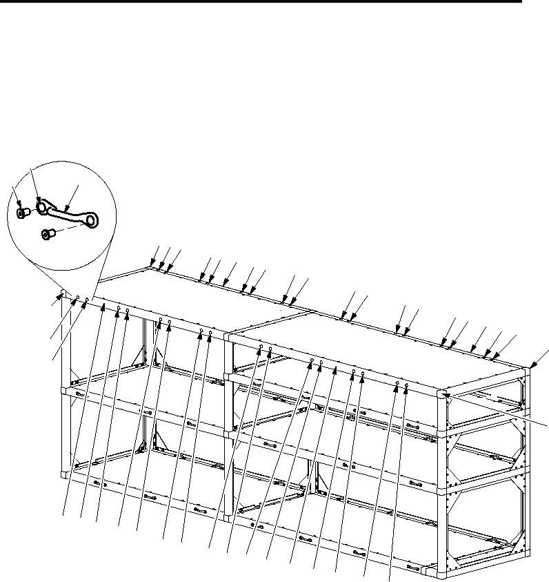
Figure 13. Curbside Rack Assembly First Shelf
1.
On forward facing area of front aluminum rail (Figure 13, Item 40) measure from outside edge of corner
casting (Figure 13, Item 43) from left towards right 5.51 inches and from top of aluminum rail (Figure 13, Item
40) towards bottom 0.75 inches and mark measurement (Figure 13, Item 42).
2.
At marked measurement (Figure 13, Item 42) position left side mounting hole (Figure 13, Item 2) of strap
fastener loop (Figure 13, Item 3) center on marked measurement (Figure 13, Item 42).
3.
Center punch left and right side mounting hole (Figure 13, Item 2) of strap fastener loop (Figure 13, Item 3)
onto aluminum rail (Figure 13, Item 40).
001420