
b. Cleaning and Inspection.
(1) Clean all parts with an approved cleaning
solvent and dry thoroughly.
(2) Inspect tool clips for cracks and dents.
Replace damaged clips.
c. Installation. Refer to figure 76 and install the
tool clip to the shop set body.
113. Box LOOPS
box loop from the shop set body.
b. Cleaning and Inspection.
(1) Clean all parts with an approved cleaning
installation.
solvent. and dry thoroughly.
(2) Inspect the box loop for cracks and dents.
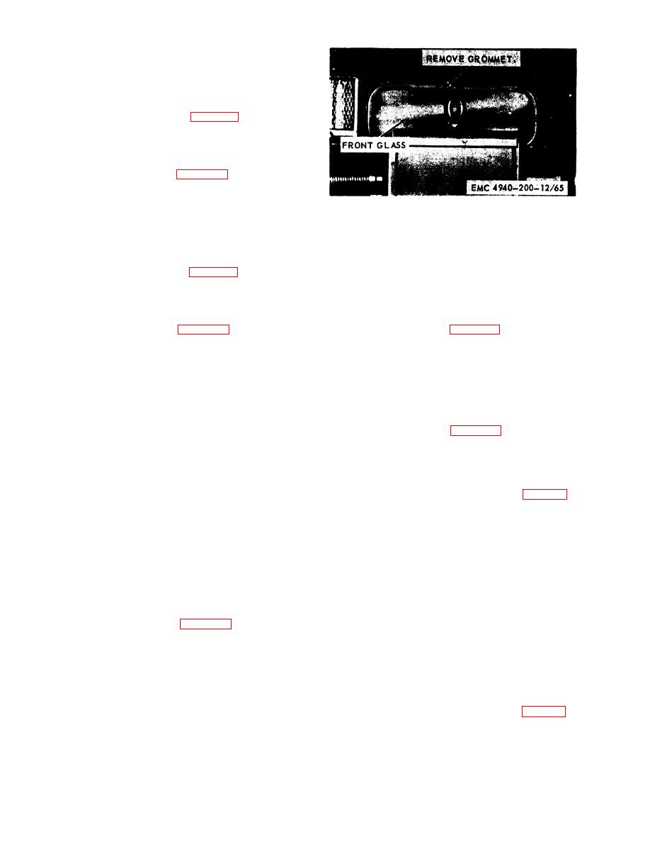
b. Cleaning and Inspection.
Replace damaged box loops.
(1) Clean the parts with a cloth dampened with
c. Installation. Refer to figure 76 and install the
a n approved cleaning solvent and dry
box loop to the shop set body.
thoroughly.
(2) Inspect the front glass for cracks. Replace
114. Front Glass and Grommet
the grommet and glass when necessary.
c. Installation. Refer to figure 77 and install the
front glass and grommet to the shop set body.
front glass and grommet from the shop set body.
Section XIII. FUEL TANK FILLER TUBE, FILLER TUBE SUPPORT, HORN BRACKET,
TAILLIGHT BRACKET, TURN SIGNAL LAMP ASSEMBLIES, AND DIRECTIONAL SIGNAL
CONTROL AND FLASHER
115. General
fuel tank filler tube to the shop set body.
The fuel tank filler tube and filler tube support are
located on the left side at the rear of the shop set
body. The horn bracket is located under the engine
a. Removal.
hood on the left side of the engine. The taillight
(1) Remove the fuel tank filler tube (par. 116).
brackets are located at the rear and on the left and
(2) Refer to figure 79 and remove the filler
right sides of the truck chassis. The taillight bracket
tube support from the shop set body.
on the left side has a lower bracket that contains a
power receptacle. The turn signal lamp assemblies
b. Cleaning and Inspection.
are located on the front and rear of the Model
(1) Clean all parts with an approved cleaning
CMU-5 shop set. The directional signal control is
solvent and dry thoroughly.
located on the steering post and the flasher is
(2) Inspect the filler tube support for cracks
located under the dash on Model CMU-5 shop set.
and dents. Replace a defectivc filler tube
support.
c. Installation.
(1) Refer to figure 79 and install the filler tube
fuel tank filler tube from the shop set body.
support to the shop set body.
b. Cleaning and Inspection.
(2) Install the fuel tank filler tube (pm. 116).
(1) Clean the parts with an approved cleaning
solvent. and dry thoroughly.
118. Splash Shield Spring and Bracket
(2) Inspect the fuel tank filler tube for cracks,
a. Removal.
holes, and dents. Replace a defective
filler tube.
TAGO 5672-.%
