
0043 00
TM 1-4920-438-13&P
INSPECTION OF INSTALLED ITEMS
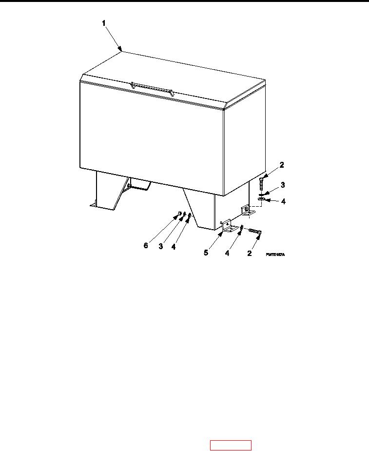
Figure 1.
Degreaser Brackets and Hardware..
NOTE
Drain degreaser prior to performing maintenance IAW with degreaser owner s manual.
1.
Inspect degreaser and degreaser brackets (Figure 1) for damage. Replace as necessary.
2.
Inspect degreaser brackets hardware Figure 1, Item 2, 3, 4 and 6) for rust, cracks and rounded heads.
Replace as necessary.
REMOVAL
1.
Remove four bolts Figure 1, Item 2), four lock washers (Figure 1, Item 3), and four lat washers (Figure 1,
Item 4) detaching brackets (Figure 1, Item 5) from loor.
2.
Remove four bolts (Figure 1, Item 2), eight lat washers (Figure 1, Item 4), four lock washers (Figure 1, Item
3), and four nuts (Figure 1, Item 6) detaching brackets (Figure 1, Item 5) from degreaser legs.
REPAIR OR REPLACEMENT
1.
If degreaser brackets (Figure 1, Item 5) can be repaired by welding, weld damaged area IAW TM
1-1500-204-23. Repair must not interfere with form, it, or function of degreaser brackets (Figure 1, Item 5).
2.
Paint repaired degreaser brackets (Figure 1, Item 5) IAW WP 0063 00, Figure 6.
INSTALLATION
1.
If a new degreaser (Figure 1, Item 1) will be installed:
0043 00-2