
TM 1-4920-438-13&P
FIELD MAINTENANCE
POWER TRAIN SHOP
MAINTENANCE INSTRUCTIONS FOR CYLINDER BRACKET ASSEMBLY AND HARDWARE
INITIAL SETUP:
Personnel Required (cont.)
Tools and Special Tools
General Mechanics Tool Kit
CMF 15 Series (1)
(WP 0067 00, Table 2, Item 104 )
References
Paint Brush (WP 0067 00, Table 2, Item 107 )
Torque Wrench, 0-600 in. lbs
TM 1-1500-204-23
(WP 0067 00, Table 2, Item 109 )
Equipment Condition
Personnel Required
Cylinder Kit Removed
CMF 15 Series Metal Worker (1)
NOTE
During installation of components same hardware should be used so as to maintain original
integrity of shop set.
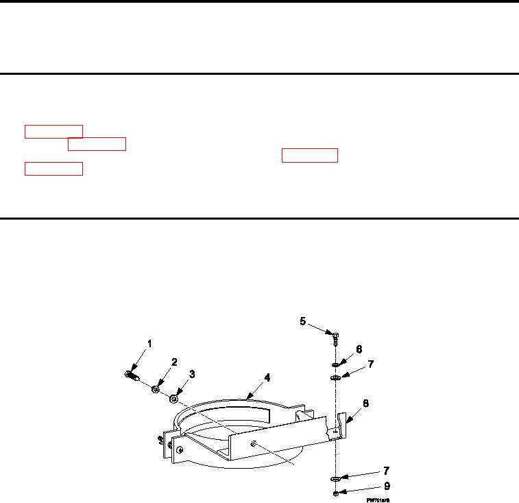
INSPECTION OF INSTALLED ITEMS
Figure 1.
Cylinder Bracket Assembly.
1.
Inspect cylinder bracket assembly (Figure 1) for damage. Replace as necessary.
2.
Inspect cylinder bracket hardware (Figure 1, Item 1, 2, 3, 5, 6,7 and 9) for rust, cracks and rounded heads.
Replace as necessary.
REMOVAL
1.
Remove two bolts Figure 1, Item 1), two lock washers (Figure 1, Item 2), and two lat washers (Figure 1, Item
3) detaching cylinder bracket assembly (Figure 1, Item 8) from wall.
2.
Remove two bolts (Figure 1, Item 5), two lat washers (Figure 1, Item 6), two lock washers (Figure 1, Item 9),
and two nuts (Figure 1, Item 6) cylinder bracket assembly (Figure 1, Item 8 from cyclinder bracket.
0044 00-1