
0012
TM 1-4920-924-13&P
AVIATION SHOP EQUIPMENT CONTACT MAINTENANCE (AV SECM) SYSTEM MAINTENANCE
INSTRUCTIONS FOR ROADSIDE RACK ASSEMBLY - (CONTINUED)
10
7
11
9
15
12
13
8
31
14
11
23
30 29
27 26
25
16
24
19
17
18
20
21
28
22
11
SECM0027
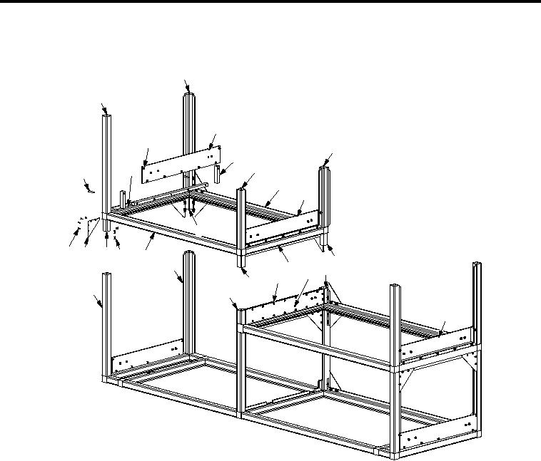
Figure 5.
Roadside Rack Assembly Third Shelf (Sheet 2 of 2).
1.
Remove sixteen 1/4-20 X 0.50 inch low head screws (Figure 5, Item 3), sixteen self clinching nuts
(Figure 5, Item 4) and two shelf assemblies (Figure 5, Item 5).
2.
Remove sixteen 1/4-20 X 0.63 inch low head screws (Figure 5, Item 2), sixteen self clinching nuts
(Figure 5, Item 6), and four drawer slides (Figure 5, Item 1).
NOTE
Mark or number parts to ensure parts are installed in the same orientation and location they
were removed from.
3.
Remove twenty-one 1/4-20 X 1.75 inch pan head screws (Figure 5, Item 31), twenty-one self clinching nuts
(Figure 5, Item 9), three drawer slide mounting plates (Figure 5, Item 11) and nine shims (Figure 5, Item 12).
4.
Remove seven 10-32 X 0.88 inch countersunk screws (Figure 5, Item 20), and seven speed nuts
(Figure 5, Item 26) from top of support plate (Figure 5, Item 18).
5.
Remove twenty-four 10-32 X 0.63 inch countersunk screws (Figure 5, Item 30), twenty-four speed nuts
(Figure 5, Item 26), and six large gussets (Figure 5, Item 29).
00129