
0014
TM 1-4920-924-13&P
AVIATION SHOP EQUIPMENT CONTACT MAINTENANCE (AV SECM) SYSTEM MAINTENANCE
INSTRUCTIONS FOR STRAP FASTENER LOOPS - (CONTINUED)
28. Install four strap fastener loops (Figure 8, Item 9) to aluminum rail (Figure 8, Item 17) by installing eight
11/64 inch blind rivets (Figure 8, Item 10) into mounting holes (Figure 8, Item 8) of four strap fastener
loops (Figure 8, Item 9).
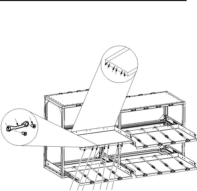
Roadside Rack Assembly Third Shelf (Left Slide Out Shelf)
4
5
6
7
8
9
3
2
1
12 11 10
16
13
15 14
SECM0075
Figure 9. Roadside Rack Assembly Third Shelf (Left Slide Out Shelf)
1.
On front side of slide out shelf assembly (Figure 9, Item 16) measure from left edge of slide out shelf assembly
(Figure 9, Item 16) towards right 8.06 inches and from top of slide out shelf assembly (Figure 9, Item 16)
towards bottom 0.75 inches and mark measurement (Figure 9, Item 15).
2.
At marked measurement (Figure 9, Item 15) position left side mounting hole (Figure 9, Item 1) of strap
fastener loop (Figure 9, Item 2) center on marked measurement (Figure 9, Item 15).
3.
Center punch left and right side mounting hole (Figure 9, Item 1) of strap fastener loop (Figure 9, Item 2)
onto slide out shelf assembly (Figure 9, Item 16).
4.
On front side of slide out shelf assembly (Figure 9, Item 16) measure from left edge of slide out shelf assembly
(Figure 9, Item 16) towards right 18.69 inches and from top of slide out shelf assembly (Figure 9, Item 16)
towards bottom 0.75 inches and mark measurement (Figure 9, Item 13).
001412