
0014
TM 1-4920-924-13&P
AVIATION SHOP EQUIPMENT CONTACT MAINTENANCE (AV SECM) SYSTEM MAINTENANCE
INSTRUCTIONS FOR STRAP FASTENER LOOPS - (CONTINUED)
Roadside Rack Assembly Second Shelf
9
8
10
7
6
5
4
3
2
1
11
13
12
14
15
16
17
18
19
20
21
22
23
SECM0074
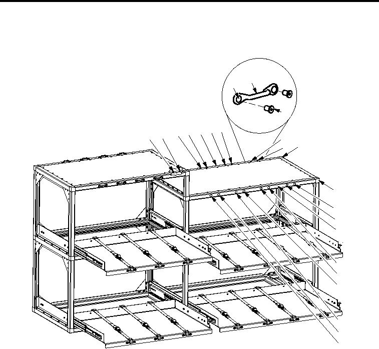
Figure 8. Roadside Rack Assembly Second Shelf
1.
On top of rear aluminum rail (Figure 8, Item 5) measure from outside edge of corner casting (Figure 8, Item
13) from right towards left 9.61 inches and from front of aluminum rail (Figure 8, Item 5) towards back 0.75
inches and mark measurement (Figure 8, Item 12).
2.
At marked measurement (Figure 8, Item 12) position right side mounting hole (Figure 8, Item 8) of strap
fastener loop (Figure 8, Item 9) center on marked measurement (Figure 8, Item 12).
3.
Center punch right and left side mounting hole (Figure 8, Item 8) of strap fastener loop (Figure 8, Item 9)
onto aluminum rail (Figure 8, Item 5).
4.
On top of rear aluminum rail (Figure 8, Item 5) measure from outside edge of corner casting (Figure 8, Item
13) from right towards left 19.16 inches and from front of aluminum rail (Figure 8, Item 5) towards back 0.75
inches and mark measurement (Figure 8, Item 7).
5.
At marked measurement (Figure 8, Item 7) position right side mounting hole (Figure 8, Item 8) of strap
fastener loop (Figure 8, Item 9) center on marked measurement (Figure 8, Item 7).
6.
Center punch right and left side mounting hole (Figure 8, Item 8) of strap fastener loop (Figure 8, Item 9)
onto aluminum rail (Figure 8, Item 5).
001410