Proper precautions must be exercised to
protect personnel Stand clear of all
tubing openings After cleaning, drain
tubes
and
dry
with
low
pressure
compressed air (30 psig, 207 kPa
maximum)
(2)
Clean inside and outside surfaces of tubing
and flex hose assemblies with compressed
air, pressurized hot water and detergent or
steam.
c.
Inspection. Refer to paragraph 6-3-b for general
inspection procedures.
(1)
Damaged gauges.
(2)
Damaged cam lever and hand valves
(3)
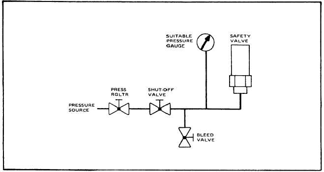
Test safety valves Connect valve to be
tested to a gauge and regulated 4,000 psig
(27,580 kPa) air or nitrogen source (see
Figure 6-3).
Keep unprotected parts of body away
from valve opening during test
NOTE
Hydrostatic tester may be used in lieu of
nitrogen or air pressure source.
(a)
Starting
with
zero
pressure
Increase
pressure to valve operating pressure.
(b)
If safety valve relieves pressure prior to, or
after specified pressure and cannot be
reset, safety valve is defective
d.
Repair or Replacement. Refer to paragraph 6-
3.c. for general repair or replacement procedures.
(1)
Replace damaged or defective nipples,
couplings and gauges.
(2)
Replace all threaded parts having worn,
stripped, or damaged threads.
(3)
Replace damaged or defective tubing.
(4)
Replace damaged or defective fittings.
(5)
Replace identification plates If damaged, or
if markings are Illegible.
(6)
Straighten bent or dented panel.
Figure 6-3. Typical Safety Valve Test Setup
6-7


