f.
Repeat steps b through e for cylinder number
two.
g.
Attach cylinder head cover to cylinder head.
h.
Install glow plug in cylinder head cover.
i.
Reconnect negative battery cable to negative
terminal of battery.
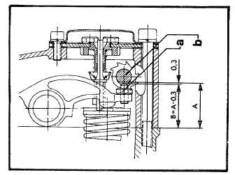
5-21. ENGINE COMPRESSION ADJUSTMENT (See
Figures 5-15, 16). To check the compression and to
adjust compression, proceed as follows:
a.
Turn flywheel in direction of rotation until
compression resistance is first noticed.
b.
Check and record measurement "A" (see figure
5-16).
In the decompressed position, the valve
must open just far enough so that the
engine can be turned over without
resistance. Do not allow the valve to
touch the piston.
c.
Loosen lock nut (a) and adjustment screw (6)
using a feeler gauge set at 0.012 inch (0.3 mm).
Using a pair of pliers, adjust screw.
d.
Tighten lock nut (a) while holding adjustment
screws (b) with pliers. Recheck for correct
clearance after lock nut (a) is tightened.
5-22. Fuel Injector Nozzle Replacement (Figure 5-17).
To replace the fuel injector nozzle, proceed as follows:
Figure 5-16. Engine Compression Adjustment
Tolerances
a.
Using a 12 mm wrench unscrew the banjo bolts
attaching the fuel leak-off lines to the injectors.
Remove fluid passage bolt, gaskets, and spacer
from injector and fuel leak-off hose.
b.
Disconnect fuel lines at fuel injectors. Remove
fuel injector from cylinder head.
c.
Remove two M8 nuts and lock washers from
injector clamp using a 13 mm wrench. Remove
fuel injector clamp.
d.
To disassemble fuel injector, unscrew nozzle
holder from retainer nut. Remove shims,
pressure spring, pressure spindle, intermediate
disc, and nozzle from nozzle holder.
e.
Replace nozzle with a new nozzle.
NOTE
Test repaired fuel injector in accordance
with instructions set forth in Section VI,
paragraph 6-39, Fuel Injector Assembly.
f.
Place new nozzle, intermediate disc, pressure
spindle, pressure spring, and shims in retainer
nut. Coat threads of nozzle holder with a light
coating of oil, per Military Specification MILL-
2104 or equivalent. Screw nozzle holder into
retainer nut. Tighten holder to 63 pounds-foot
(85Nm) torque.
Make
certain
washer
is
properly
positioned in cavity of cylinder head.
g.
Place assembled fuel injector in cavity of cylinder
head.
h.
Place clamp over injector.
i.
Attach clamp to cylinder head using two washers
and nuts.
j.
Connect fuel pressure lines to injector.
k.
Connect fuel leak-off hose to injector using
spacer, washers, and a fluid passage bolt.
l.
Repeat steps a through k for fuel injector
number two.
5-24. LUBRICATION INSTRUCTIONS. Points of
lubrication, type of lubricant, application, and time
interval are listed in Table 5-3. Detailed instructions are
as follows:
NOTE
So oil will flow more freely, drain oil from
the engine crankcase while the engine is
hot.
5-14


