
TM 1-4920-436-13&P
FIELD MAINTENANCE
ENGINE SHOP
MAINTENANCE INSTRUCTIONS FOR ULTRASONIC CLEANER, GENERATOR, AND HARDWARE
INITIAL SETUP:
Personnel Required (cont.)
Tools and Special Tools
General Mechanics Tool Kit
CMF 44B Metal Worker (1)
(WP 0060 00, Table 2, Item 104 )
References
Paint Brush (WP 0060 00, Table 2, Item 107 )
Torque Wrench, 0-600 in. lbs
Degreaser Owner s Manual
(WP 0060 00, Table 2, Item 109 )
Equipment Condition
Personnel Required
Functional
CMF 15 Series (2)
NOTE
During installation of components same hardware should be used so as to maintain original
integrity of shop set.
INSPECTION OF INSTALLED ITEMS
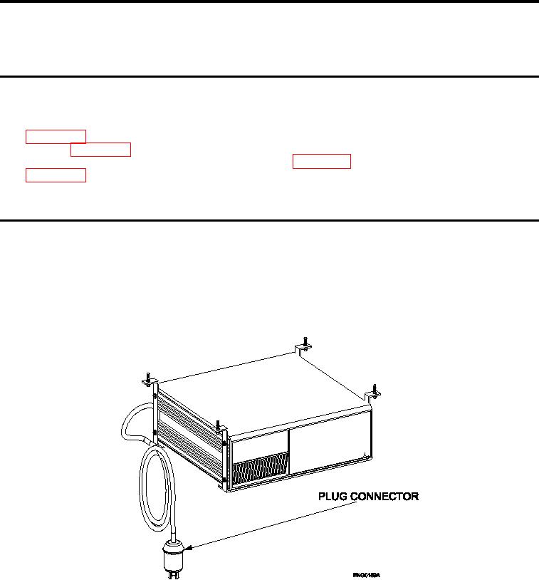
CONNECTOR PLUG
Figure 1.
Plug Connector.
With 240V connector plug unplugged, visually inspect 240V connector plug for any damage that could possibly
cause an electrical hazard.
0037 00-1