
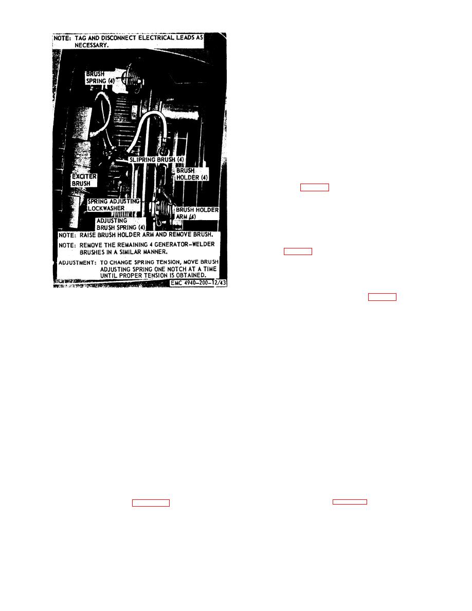
Note. Use a spring scale to check brush spring
tension. Correct tension is 32 ounces.
(2) Install end wrappers (par. 77).
a. General. Loss of residual magnetism in the
exciter field frame can be caused by long periods of
idleness, a short circuit, or a sudden surge of current
from an outside power source. Loss of magnetism .
will cause the generator-welder to fail to build up
voltage in any of its components. To magnetize the
exciter field frame follow the instructions in b below.
b. Magnetizing Exciter Field.
(1) Remove the end wrappers (par. 77).
(2) Raise the exciter brushes from the com-
mutator (par. 79).
(3) Using an outside source of direct current
(a storage battery is satisfactory), apply
the current to two adjacent exciter brushes
for a few seconds and remove the current
source.
(4) Lower the exciter brushes to the commuta-
tor (par. 79).
(5) Install the end wrapper (par. 77).
(6) Start the generator-welder (pars. 16 and
17).
(7) Place the welding polarity control switch
in the STRAIGHT position (par. 16).
(8) If the exciter fields are properly magnetized,
and adjustment.
the direct current voltmeter will indicate
voltage on the right side of the scale,
c. Brush Seating. Refer to TM 5-764.
(9) If the direct current voltmcter indicates
Note. To avoid wastage of brush material, sand only until
voltagc on the left sick of the scale, stop the
radius of commutator is obtained. Blow out carbon dust with
generator-welder (pars. 18 and 19) and
low-pressure, dry, compressed air.
repeat steps (1) and (2) above.
d. Installation.
(lo) Repeat steps (4) through (8) above and
(1) Refer to figure 55 and install the generator-
stop the generator-welder (pars. 18 and 19).
welder brushes to the generator-welder.
Section Xl. AIR COMPRESSOR
b. Cleaning and Inspection.
81. General
(1) Clean the handle with an approved clean-
The air compressor (Model SECM shop set) is a
ing solvent and dry thoroughly.
portable, diaphragm-type (Compressor with a direct
(2) Inspect the handle for dents, cracks, breaks,
drive to a 110-volt, split-phase motor. Mounted
or other damage. Replace a damaged
above the motor is the compressor head equipped
with a carrying handle. This model is designed to
handle.
start under normal or light loads.
Inspect the mounting hardware for worn
(3)
Replace as required.
or damaged threads.
82. Handle
handle to the compressor head.
compressor handle from the compressor head.
TAGO 5672-A
